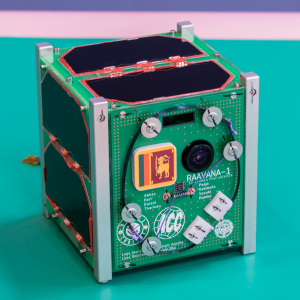
RAAVANA-1, Sri Lanka’s first nano-satellite — and the first-ever satellite of any kind built by Sri Lankans — was developed by a team of Sri Lankan engineers through an international technology-collaboration project. The project was carried out by the ACCIMT and Kyutech, positioning it within the Kyutech’s BIRDS-3 CubeSat Programme, with significant support from the United Nations Office for Outer Space Affairs (UNOOSA) and Japanese Aerospace Exploration Agency (JAXA).
It was carried to the International Space Station (ISS) on 17 April 2019 aboard the Cygnus capsule launched on the Antares rocket by NASA. On 17 June 2019, it was deployed into orbit via JAXA’s KiboCube facility on the ISS. RAAVANA-1, with five research missions onboard, operated successfully in orbit for 27 months.
Importantly, the project was realized at a fraction of the typical cost, through the innovative approach adopted by the Director-General & CEO, ACCIMT, Eng. (Dr.) Sanath Panawennage, by way of identifying and optimally mobilizing collaborative opportunities with multiple international partners, thereby overcoming domestic resource limitations.
The name RAAVANA-1, given to the satellite by Dr. Panawennage, was chosen to resonate with the legendary King Ravana of Sri Lankan folklore—renowned for his superhuman powers and said to have built an air vehicle for travel thousands of years ago.
Team Members
Eng. Dr. Sanath Panawennage Director General (ACCIMT)
Developed the project concept with an innovative strategy for mobilizing collaboration with multiple international partners, thereby overcoming domestic resource limitations, and managed its implementation. Led the Sri Lankan project team as the Principal Investigator on the Sri Lankan side.
Eng. (Ms.) Kamani Edirweera Deputy Director General (Technical)
Assisted the Director-General in project planning, monitoring, and management.
Eng. Kavindra Jayawardena Director (Communication Engineering Devision)
Assisted the Director-General in project planning, monitoring, and management. Provided general technical guidance to the research engineers.
Eng. Tharindu Dayarathna, Research Engineer (ACCIMT)
Developed and tested all subsystems to required standards, introducing necessary modifications, whilst gaining advanced capacity-building exposure at Kyutech laboratories. Made a decisive contribution to the success of the communication sub-system.
Eng. Dulani Chamika, Research Engineer (ACCIMT)
Developed and tested other subsystems to required standards, introducing necessary modifications, whilst gaining advanced capacity-building exposure at Kyutech laboratories.
Designed and developed the ground station facility at ACCIMT for communication with RAAVANA-1.
RAAVANA-1 Launch to ISS
RAAVANA-1 Deployment Preparation in ISS
RAAVANA-1 Orbit Deployment from ISS
Satellite Details
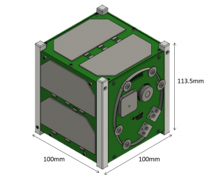
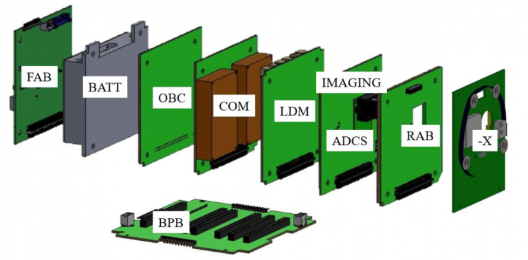
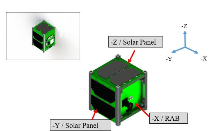
RAAVANA-1 satellite is a 1U CubeSat standard satellite. The external dimensions of the satellite are 113.5mm x 100mm x 100mm. Figure 1 shows the CAD model of RAAVANA-1 satellite with axis definition. The weight of the satellite is 1.048kg. All the printed circuit boards (PCBs) are connected using 50 pin connectors to a backplane. RAAVANA-1 satellite has four missions in total. They will be described in the below sections.
Figure 1: CAD Model of RAAVANA-1 CubeSat
Bus System
RAAVANA-1 bus system is using the heritage of BIRDS-1 and BIRDS-2 bus systems. The bus system includes Front Access Board (FAB), Electrical Power System (EPS), On Board Computer (OBC), Communication (COM) and Rear Access Board (RAB). Figure 2 shows the internal bus configuration.
Figure 2: Internal Configuration
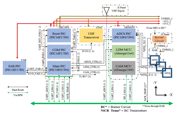
The block diagram of the overall system is shown in figure 4. The microcontrollers used in the bus system are PIC microcontrollers. A PIC16F1789 is used in the FAB board. This PIC collects housekeeping data from solar panels and battery. FAB PIC communicates with Main PIC through UART. The FAB has a kill switch which is controlled by the FAB PIC and Main PIC. Main PIC collects data from FAB PIC every 90 seconds in normal sampling mode. Moreover, Main PIC collects data from FAB every 5 seconds when it comes to high sampling mode.
The OBC includes the Main PIC and a watchdog enabled Reset PIC. The Main PIC which is a PIC18F67J94 and works as the brain of the CubeSat. PIC16F1789 is used as the RESET PIC. RESET PIC keeps the time and resets the Main PIC in case of single event latch up or any other abnormal condition. Main PIC and Reset PIC communicates through UART. Main PIC keeps the housekeeping data, sends the command to deploy the antenna, get uplink commands from COM and execute the missions accordingly. The Main PIC has its own 1GB flash memory which is a MT25QL01GB. Another flash memory is shared between COM PIC and the Main PIC.
Communication subsystem has a PIC16F1789 microcontroller (COM PIC). This PIC is located in OBC board. The responsibilities of COM PIC are to accept the command from the ground station, send those commands to Main PIC, create the CW format and transmit. COM PIC communicates with Main PIC and Reset PIC through UART lines. COM PIC has its own flash memory which is a MTQ25QL01GB 1GB except the shared flash memory. A dipole antenna is located in –X panel. The telemetry data and CW data are sent to ground station by using this antenna. The frequencies used for uplink and downlink are in the amateur radio band. The downlink frequency is 437.375 MHz.
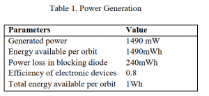
The power is generated by the solar panels attached in five sides of the satellite. Total energy generated by in one orbit is 1490mWh. The satellite has six NiMH batteries and the capacity of one battery is 1900mAh.
Reset PIC controls the power lines of the satellite. The power lines in the satellite are two 3.3V lines, one 5V line and two unregulated lines. Unregulated line is used for antenna deployment. The antenna is deployed after 30 minutes from ISS deployment. RAB is used to program and to monitor the mission microcontrollers. FAB is used to program and monitor Main PIC, FAB PIC, RESET PIC and COM PIC.
Figure 3: Block diagram of overall system
RAAVANA-1 Mission Overview
As mentioned above, RAANVANA-1 has four missions. They are Imaging Mission (CAM), LoRa Demonstration Mission (LDM), Attitude Determination and Control Mission (ADCS) and Software Configurable Backplane Mission (BPB). There are two mission boards in the satellite. They are named as Mission Board-1 and Mission Board-2.
1.LoRa Demonstration Mission
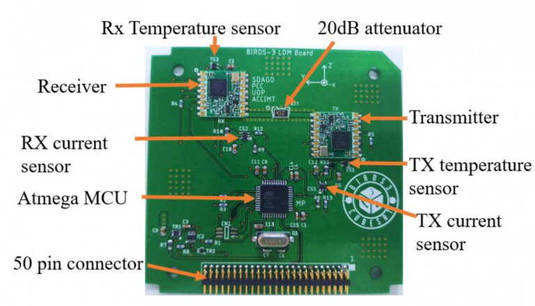
Mission Board-1 has the LoRa Demonstration Mission. The Mission Board-1 is shown in the figure 4.
Figure 4: Mission Board-1 with LDM components
This board has two RFM95W SEMTECH Long Range (LoRa) modulation transceivers, current sensors, Atmega MCU, one 20 dB attenuator and two temperature sensors. One LoRa module operates as a transmitter and the other one operates as a receiver. Atmega32U4 MCU is connected to Main PIC by a UART line. Mission Board-1 is connected to OBC through a 50-pin connector. The main focus of this mission is to verify on orbit operation of LoRa modules by sending data from one module to the other module. LoRa modules are designed to operate in Industrial, Scientific and Medical (ISM) frequency bands which is a non-amateur band. The amateur band and non-amateur band cannot be mixed in the CubeSat according International Amateur Radio Union (IARU). This means uplink by non-amateur band and downlink by amateur band is not allowed. Due to this reason the radio waves are not emitted to outside. First Transmitter LoRa module transmit a packet and then receiver decodes and sends the received data to Atmega32U4 MCU. Atmega324U4 MCU checks whether the received packets has error using cyclic redundancy check (CRC) and monitor the current consumption and the temperature values of the modules.
2. Imaging Mission (CAM)
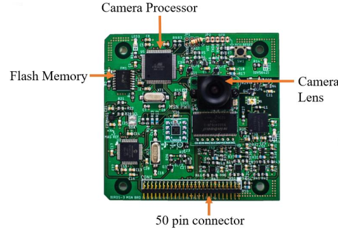
Mission Board-2 has Imaging Mission and ADCS mission hardware. The objective of the Imaging Mission is to take pictures from space primarily for media and outreach programs. Figure 5 shows the Mission Board-2 with CAM hardware.
Figure 5: Mission Board-2 with CAM hardware
The Imaging mission has a single 5-megapixel OV5642 Arducam module, 8 bit Atmega2560V MCU and 1 GB MT25QL01GB non-volatile flash memory. However, the images have been down sampled to 640 x 480, because of the low downlink speed. The lens is a commercial S mount, M12 lens from Lensation. The focal length of the length is 2.9mm and f2.0. Imaging mission is executed when the camera processor gets a command from the ground station through Main PIC and COM PIC. Mission board-2 is connected to On Board Computer by using a 50 pin connector.
3. ADCS Mission
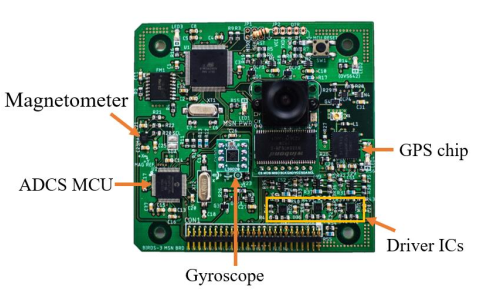
PIC18f67J94 is used as the microcontroller (MCU) for ADCS in the satellite. ADCS MCU collects data from magnetometer, gyroscope and GPS chip. The magnetometer communicates with the ADCS MCU using I2C, gyroscope communicates using SPI and GPS chip communicates using UART. ADCS MCU sends the data collected from the sensors to Main PIC via UART. The objective of the ADCS mission is to stabilize the satellite’s attitude by active control. The ADCS includes a L3GD20 Gyroscope, MMC5883 magnetometer, Venus838FLPx-L GPS chip and three A3901 Driver ICs. Figure 6 shows the Mission Board-2 with ADCS components.
Figure 6: Mission Board 2 with ADCS components
For the active stabilization, magnetic torquers (MTQ) are used as the actuator. Driver ICs are used to control the current in magnetic torquers. Control algorithm used is B dot algorithm. Magnetic torquers are printed in the Printed Circuit Boards (PCB) of –X, -Y and –Z sides of the CubeSats. –Y and –Z are solar panels boards while –X is Rear Access Board (RAB).
Figure 7 shows the location of the magnetic torquers.
Figure 7: MTQ Locations
Each MTQ has 100 turns. In each PCB layer two and layer three are used to print MTQs. In one layer there are 50 turns. The following figure shows the MTQ design of the Rear Access Board. The maximum current used for MTQ is 0.03A. Figure 8 shows the MTQ in the Rear Access Board.
Figure 8: MTQ in Rear Access Board
4. Software Backplane Mission (BPB)
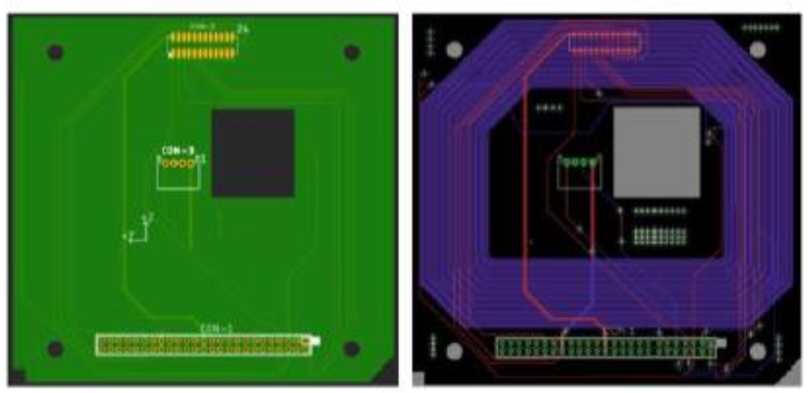
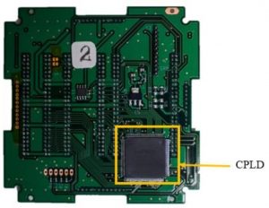
The BPB mission is to demonstrate the use of standard software configurable backplane for future CubeSat missions. The objectives are to use programming to reroute the backplane pin layout and to demonstrate that the all the missions can be done using the Software Configurable Backplane.
Figure 9: Software Configurable Backplane
An ispMACH4000ZE Complex Programmable Logic Device (CPLD) is used in this mission. Figure 10 shows the Software Configurable Backplane.
On Orbit Results
Since the satellite deployment on June 17, 2019, on-orbit behaviour of LDM was monitored. Transmitter current consumption, receiver current consumption, transmitter temperature, and receiver temperature were observed. There was no abnormal current or temperature observed until the end of the life of the satellite. All the current consumption values were closer to ground testing data. In the ground testing current consumption of the transmitter was 33mA and the current consumption of the receiver was 13mA. Packet success rate was 100 % till end of the life.
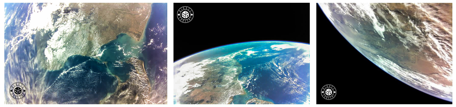
RAAVANA-1 was able to take pictures from the space. The followings are some of the pictures taken by the satellite.
BPB mission was also successful. MainPIC and LDM UART connection, Main PIC and CAM Processor UART connection, SPI line to CAM, Main PIC and ADCS UART connection and Digital Input Output (DIO) line to LDM are CPLD connections. All these CPLD connections didn’t show any failure. CAM UART line and SPI CAM line works continuously. ADCS UART line works in every 90 seconds. ADCS mission also showed promising results.
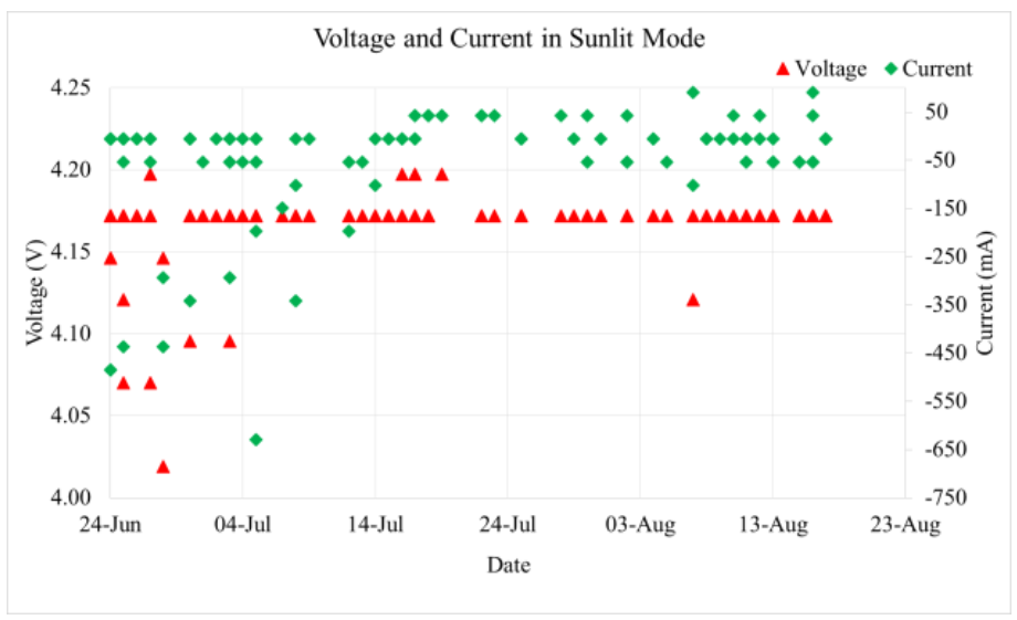
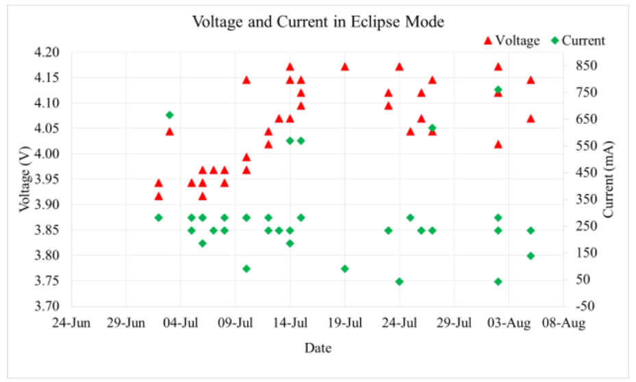
The voltage and current in sunlit mode of the satellite is shown in the following graph. In Sunlit mode battery starts charging and the voltage is around 4.2V when it is charging. Nominal current consumption is around 250mA-280mA. When the satellite is in the sunlit mode, missions are done by solar cell power. When the satellite is in eclipse mode batteries are used execute missions. According to on orbit data the voltage hasn’t reached below 3.75V. The voltage and current in sunlit and eclipse in Raavana-1 are shown in graphs below.
Figure 10: Voltage and Current in Raavana-1(Sunlit)
Figure 11: Voltage and Current in Raavana-1(Eclipse)
RAAVANA-1 Deorbiting and Conclusion
RAAVANA-1 deorbited on 03rd of October 2021 after about 28 months from deployment. In the life time of the satellite all the mission of the satellite were executed successfully. There was no any system failure.